ArtyZ7 tutorial for 4.3” TFT LCD screen support

This tutorial will explain how to drive a 4.3” TFT LCD using a Digilent ArtyZ7 based on Xilinx Zynq programmable SoC.

Autore - Ing. Federico Civerchia

The LCD screen is driven through the SPI interface instantiated on the FPGA and controlled by the processing system. In particular, we will see how to instantiate both the SPI on EMIO and using the axi quad SPI IP core.
The devices used for this tutorial are listed below:
– Digilent Arty Z7
– EastRising 4.3″LCD Touch
– Screen Module Display based on RA8875 controller
– Micro USB cable to connect the Arty to the PC
– 5V power supply for the Arty
– Prototype Cable (Male to Female)
– Strip 2×4 (pitch 2.54 mm) to be soldered on the screen to export the SPI pins

Tools:
– Vivado 2016.3
– SDK 2016.3

Design
We start creating a new project from Vivado: go to File -> New Project and select the Arty Z7 board when the Default Part window appears (image above).
Once the project is created, we can start the block design. Under IP integrator field on the menu on the left, select “Create Block Design”.
Thus, we have to add the necessary blocks for our purpose. First of all, we add the ZYNQ7 Processing System block. Doble click on the instance created to re-customize the IP, click on the Peripheral I/O when the window appears and set the SPI0 as EMIO (image below).

We also have to create another instance of the SPI based on the axi_quad_spi IP core. This is the SPI implemented in the programmable logic (FPGA) while the EMIO SPI is directly implemented on the processing system (ARM Cortex A9) even if it uses the FPGA pins.
We have to instantiate the AXI Quad SPI block on the design and re-customize the IP doing double-click on the instance (as we have done for the Zynq). Under IP configuration, we have to set the following parametrer:

Mode: Standard
Transaction Width: 8
Frequency ratio: 8×1
Enable master mode
Enable FIFO
FiFo depth: 16

After this step, we can select the Run Block Automation and Run Connection Automation to automate the connection and block

A little explanation in depth is necessary for the Frequency ratio: the Zynq FPGA bus frequency is 100MHz (as set in the Zynq clock configuration) while the LCD needs at maximum 5 MHz SPI clock, thus we have to scale the frequency. For this reason, we put a PLL (clock_wizard IP) between the Fabric clock and the AXI Quad SPI clock. The output of the PLL will be 40 MHz, which corresponds to the input clock of the SPI block. As described above, we have put the frequency ratio of the AXI Quad SPI at 8, which means that the output clock of the SPI towards the LCD screen will be 5 MHz (40/8=5).
The last steps to perform is to add a constant block which is connected to both SPI0_SS_I and ss_i[0:0] pins of the SPI interfaces created (value and width of the constant are 1). The final block design is depicted in the figure below.
Note that the clk_wiz_0 block (PLL) is connected to FCLK_CLK0 (input) and ext_spi_clk (output). Once the block design is completed, we have to move on IP sources in the Sources window, right click on the design that we have created and select Create HDL Wrapper.. (referred to the figure below, our design is named design_1 and it is necessary to right click on it and select Create HDL Wrapper. )

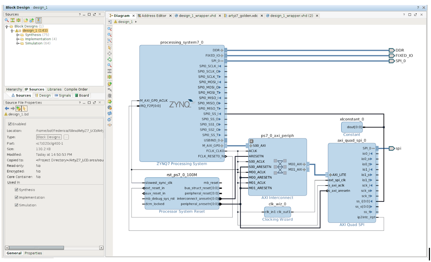
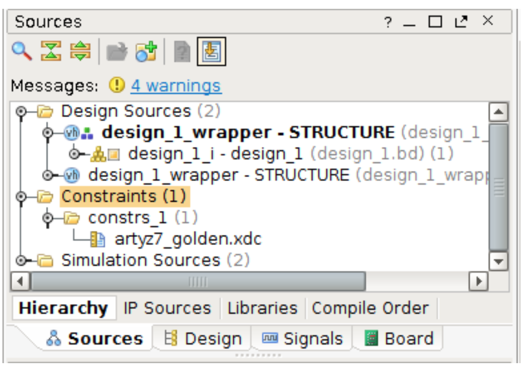
Now we have to map the signals exported in HDL wrapper to the physical pins of the board. In the following we listed the changes that we have done in the artyz7_golden.xdc file located in Constraints directory under source window.

Finally we are ready to generate the bitstream!

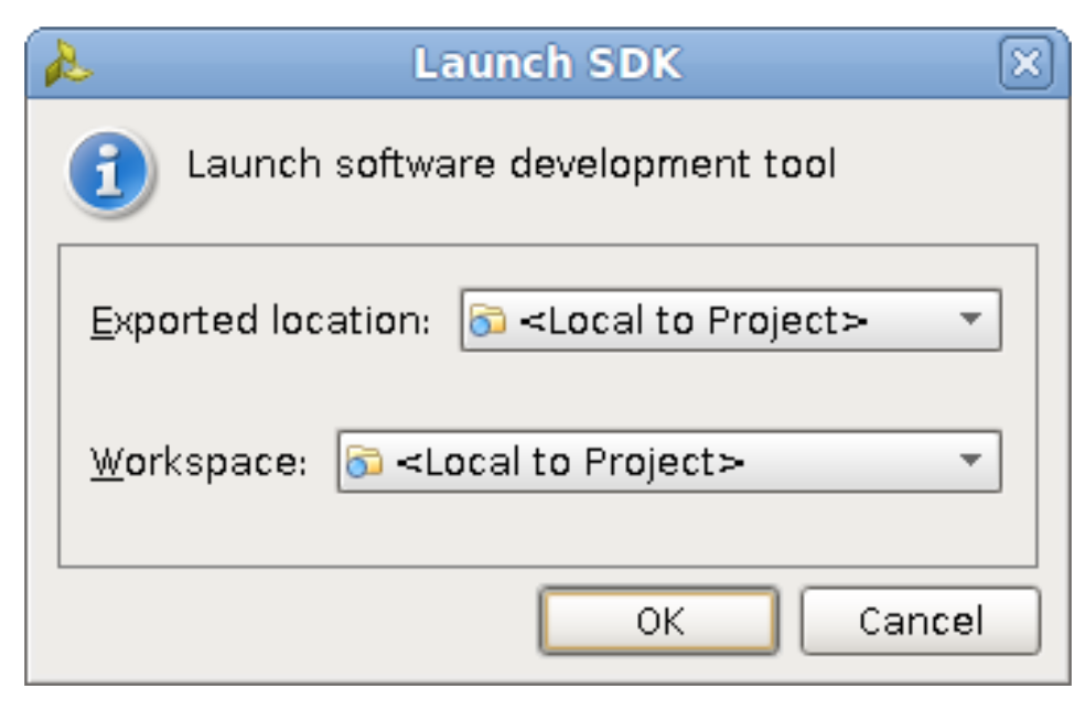
While bitstream is performing, we can launch SDK tool.

##Pmod Header JA

set_property -dict { PACKAGE_PIN Y18 IOSTANDARD LVCMOS33 } [get_ports { spi_0_io0_io }]; #IO_L17P_T2_34 Sch=JA1_P

set_property -dict { PACKAGE_PIN Y19 IOSTANDARD LVCMOS33 } [get_ports { spi_0_io1_io }]; #IO_L17N_T2_34 Sch=JA1_N
set_property -dict { PACKAGE_PIN Y16 IOSTANDARD LVCMOS33 } [get_ports { spi_0_sck_io }]; #IO_L7P_T1_34 Sch=JA2_P
set_property -dict { PACKAGE_PIN Y17 IOSTANDARD LVCMOS33 } [get_ports { spi_0_ss_o }]; #IO_L7N_T1_34 Sch=JA2_N
set_property -dict { PACKAGE_PIN U18 IOSTANDARD LVCMOS33 } [get_ports { spi_io0_io }]; #IO_L12P_T1_MRCC_34 Sch=JA3_P
set_property -dict { PACKAGE_PIN U19 IOSTANDARD LVCMOS33 } [get_ports { spi_io1_io }]; #IO_L12N_T1_MRCC_34 Sch=JA3_N
set_property -dict { PACKAGE_PIN W18 IOSTANDARD LVCMOS33 } [get_ports { spi_sck_io }]; #IO_L22P_T3_34 Sch=JA4_P
set_property -dict { PACKAGE_PIN W19 IOSTANDARD LVCMOS33 } [get_ports { spi_ss_o }]; #IO_L22N_T3_34 Sch=JA4_N 
##Pmod Header JB

set_property -dict { PACKAGE_PIN Y14 IOSTANDARD LVCMOS33 } [get_ports { spi_0_ss1_o }]; #IO_L8N_T1_34 Sch=JB1_N
set_property -dict { PACKAGE_PIN W14 IOSTANDARD LVCMOS33 } [get_ports { spi_0_ss2_o }]; #IO_L8P_T1_34 Sch=JB1_P
set_property -dict { PACKAGE_PIN T10 IOSTANDARD LVCMOS33 } [get_ports { spi_0_ss_t }]; #IO_L1N_T0_34 Sch=JB2_N 

Generate a Device Tree Source (.dts/.dtsi) files from SDK

1. Vivado Menu: File > Launch SDK
2. The Device Tree Generator Git repository needs to be cloned from the Xilinx. See the Fetch Sources page for more information on Git.
3. # Otherwise for SDK 2014.2 use this repo:
git clone git://github.com/Xilinx/device-tree-xlnx.git

4. Add the BSP repository in SDK (for SDK 2014.2 and later select “device-tree-xlnx” from the checked out git area): SDK Menu: Xilinx Tools > Repositories > New… () > OK
5. Create a Device Tree Board Support Package (BSP): SDK Menu: File > New > Board Support Package > Board Support Package OS: device-tree > Finish
6. These steps create a .dtsi and programmable logic dts and processing system dts under .sdk directory in the workspace, all included in a system-top.dts that has to be compiled with:

dtc -I dts -O dtb -o .dtb system-top.dts 

Generate FSBL from SDK

1. Click File > New > Application Project
2. Note: This is equivalent to clicking on File > New > Project to open the New Project wizard, selecting Xilinx > Application Project, and clicking Next
3. The New Application Project dialog box appears
4. In the Project Name field, type a name for the new project
5. Select the location for the project. To use the default location as displayed in the Location field, leave the Use default location check box selected. Otherwise, click to unselect the checkbox, then type or browse to the directory location
6. The Hardware Platform is related to the wrapper created in Vivado
7. Leave the Target software as is

8. Click Next
9. In the Templates dialog box, select the Zynq FSBL template
10. Click Finish to create your application project and board support package (if it does not exist)

Compile U-boot

  1. Open a terminal
2. git clone https://github.com/Digilent/u-boot-digilent.git u-boot-digilent
3. cd u-boot-digilent 

4. move to the newest branch using the git checkout command
5. The u-boot.elf is in the current folder

6. source //settings64.sh
7. export ARCH=arm
8. export CROSS_COMPILE=arm-xilinx-linux-gnueabi-
9. make zynq_artyz7_defconfig
10. make 

11. The u-boot.elf is in the current folder

Create BOOT image from SDK

  1. Click Xilinx tools > create boot image
  2. Create New BIF file and set the path for the output BIF and BIN
  3. Add the FSBL, the bitstream and the u-boot.elf (add the files in this order!!)
  4. Click create image: the image created will be BOOT.bin named

Compile kernel

  1. Open a terminal
2. git clone https://github.com/Xilinx/linux-xlnx.git linux-xlnx
3. cd linux-xlnx 

4. move to the newest branch using the git checkout command
5. Exe the followings:

source //settings64.sh
export ARCH=arm
export CROSS_COMPILE=arm-xilinx-linux-gnueabi-
make xilinx_zynq_defconfig
make xconfig 

6. Add the TFT LCD display support and check SPI support (see the images below)
Note: we prefer to load the kernel module for the generic FB driver for TFT LCD display as external module. The TFT LCD support can be added to the kernel following this steps:

7. cd drivers/video/
8. git clone https://github.com/notro/fbtft.git
9. # Let make/kbuild see the directory and config options.
10. echo "obj-y += fbtft/" >> Makefile
11. sed -i 's/endmenu/source "drivers\/video\/fbtft\/Kconfig"\n\nendmenu/' Kconfig 

12. save configuration

13. make UIMAGE_LOADADDR=0x8000 uImage 

Compile the rootfs

  1. Debian rootfs can be downloaded from: ftp://ftp.debian.org/debian/
  2. With QEMU, it can be cross compiled for the ARM architecture with:
qemu-debootstrap --no-check-gpg --arch=armhf sid /chroots/sid-armhf ftp://ftp.debian.org/debian/ 

3. At the end of this process, in /chroots/sid-armhf you might find the ARM-compiled root filesystem. Just a copy and paste into the target rootfs folder will do the rest.

Create the SD for ArtyZ7

Note: we use a 8 GB SD

  1. Create a BOOT partition (FAT32) of 200MB
  2. Create a rootfs partition (ext4) with the rest of SD space
  3. Copy on the BOOT partition the BOOT.bin, the dtb and the uImage create previously plus the uramdisk.image.gz that can be downloaded online
  4. For the rootfs, see step 3 on “compile the rootfs”

We are ready to plug the sdcard on the ArtyZ7. Remember to import the fbtft_device.ko kernel module once the system is up on the Arty. You can use a scp command or a memory stick to import the module. It is located in the linux-xilinx/drivers/video/fbtft
Set up your system as you prefer and then load the kernel module for the TFT LCD considered for this tutorial with the command:

sudo insmod fbtft_device.ko busnum= name=er_tftm050_2 

And that’s all! Have fun!

If you enjoyed this tutorial, spread the word!